Chapter 15-Transition to Jet Powered Airplanes
Table of Contents
General
Jet Engine Basics
Operating the Jet Engine
Jet Engine Ignition
Continuous Ignition
Fuel Heaters
Setting Power
Thrust to Thrust Lever Relationship
Variation of Thrust with RPM
Slow Acceleration of the Jet Engine
Jet Engine Efficiency
Absence of Propeller Effect
Absence of Propeller Slipstream
Absence of Propeller Drag
Speed Margins
Recovery from Overspeed Conditions
Mach Buffet Boundaries
Low Speed Flight
Stalls
Drag Devices
Thrust Reversers
Pilot Sensations in Jet Flying
Jet Airplane Takeoff and Climb
V-Speeds
Pre-Takeoff Procedures
Takeoff Roll
Rotation and Lift-Off
Initial Climb
Jet Airplane Approach and Landing
Landing Requirements
Landing Speeds
Significant Differences
The Stabilized Approach
Approach Speed
Glidepath Control
The Flare
Touchdown and Rollout

SPEED MARGINS
The typical piston powered airplane had to deal with two maximum operating speeds.
- ò VNOùMaximum structural cruising speed, represented on the airspeed indicator by the upper limit of the green arc. It is, however, permissible to exceed VNO and operate in the caution range (yellow arc) in certain flight conditions.
- ò VNEùNever-exceed speed, represented by a red line on the airspeed indicator. These speed margins in the piston airplanes were never of much concern during normal operations because the high drag factors and relatively low cruise power settings kept speeds well below these maximum limits.
Maximum speeds in jet airplanes are expressed differently, and always define the maximum operating speed of the airplane which is comparable to the VNE of the piston airplane. These maximum speeds in a jet airplane are referred to as:
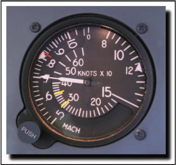
ò VMOùMaximum operating speed expressed in terms of knots. ò MMOùMaximum operating speed expressed in terms of a decimal of Mach speed (speed of sound).To observe both limits VMO and MMO, the pilot of a jet airplane needs both an airspeed indicator and a Machmeter, each with appropriate red lines. In some general aviation jet airplanes, these are combined into a single instrument that contains a pair of concentric indicators, one for the indicated airspeed and the other for indicated Mach number. Each is provided with an appropriate red line. [Figure 15-8]
Ch 15.qxd 5/7/04 10:22 AM Page 15-7
Figure 15-8. Jet airspeed indicator.
A more sophisticated indicator is used on most jetliners. It looks much like a conventional airspeed indicator but has a ôbarber poleö that automatically moves so as to display the applicable speed limit at all times.
Because of the higher available thrust and very low drag design, the jet airplane can very easily exceed its speed margin even in cruising flight, and in fact in some airplanes in a shallow climb. The handling qualities in a jet can change drastically when the maximum operating speeds are exceeded.
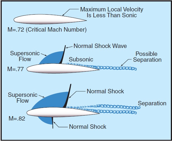
High speed airplanes designed for subsonic flight are limited to some Mach number below the speed of sound to avoid the formation of shock waves that begin to develop as the airplane nears Mach 1.0. These shock waves (and the adverse effects associated with them) can occur when the airplane speed is substantially below Mach 1.0. The Mach speed at which some portion of the airflow over the wing first equals Mach 1.0 is termed the critical Mach number (MACHCRIT). This is also the speed at which a shock wave first appears on the airplane.
If allowed to progress well beyond the MMO for the airplane, this separation of air behind the shock wave can result in severe buffeting and possible loss of control or "upset."
Because of the changing center of lift of the wing resulting from the movement of the shock wave, the pilot will experience pitch change tendencies as the airplane moves through the transonic speeds up to and exceeding MMO. [Figure 15-10]
Figure 15-10. Example of Stick Forces vs. Mach Number in a typical jet airplane.
There is no particular problem associated with the acceleration of the airflow up to the point where Mach 1.0 is encountered; however, a shock wave is formed at the point where the airflow suddenly returns to subsonic flow. This shock wave becomes more severe and moves aft on the wing as speed of the wing is increased, and eventually flow separation occurs behind the well-developed shock wave. [Figure 15-9]

Figure 15-9. Transonic flow patterns.
For example, as the graph in figure 15-10 illustrates, initially as speed is increased up to Mach .72 the wing develops an increasing amount of lift requiring a nose- down force or trim to maintain level flight. With increased speed and the aft movement of the shock wave, the wingÆs center of pressure also moves aft causing the start of a nosedown tendency or ôtuck.ö By Mach .83 the nosedown forces are well developed to a point where a total of 70 pounds of back pressure are required to hold the nose up. If allowed to progress unchecked, Mach tuck may eventually occur. Although Mach tuck develops gradually, if it is allowed to progress significantly, the center of pressure can move so far rearward that there is no longer enough elevator authority available to counteract it, and the airplane could enter a steep, sometimes unrecoverable dive.
Ch 15.qxd 5/7/04 10:22 AM Page 15-8An alert pilot would have observed the high airspeed indications, experienced the onset of buffeting, and responded to aural warning devices long before encountering the extreme stick forces shown. However, in the event that corrective action is not taken and the nose allowed to drop, increasing airspeed even further, the situation could rapidly become dangerous. As the Mach speed increases beyond the airplaneÆs MMO, the effects of flow separation and turbulence behind the shock wave become more severe. Eventually, the most powerful forces causing Mach tuck are a result of the buffeting and lack of effective downwash on the horizontal stabilizer because of the disturbed airflow over the wing. This is the primary reason for the development of the T-tail configuration on some jet airplanes, which places the horizontal stabilizer as far as practical from the turbulence of the wings. Also, because of the critical aspects of high-altitude/high-Mach flight, most jet airplanes capable of operating in the Mach speed ranges are designed with some form of trim and autopilot Mach compensating device (stick puller) to alert the pilot to inadvertent excursions beyond its certificated MMO.
PED Publication