Chapter 12—Transition to Multiengine Airplanes
Table of Contents
Multiengine Flight
General
Terms and Definitions
Operation of Systems
Propellers
Propeller Synchronization
Fuel Crossfeed
Combustion Heater
Flight Director / Autopilot
Yaw Damper
Alternator / Generator
Nose Baggage Compartment
Anti-Icing / Deicing
Performance and Limitations
Weight and Balance
Ground Operation
Normal and Crosswind Takeoff and Climb
Level Off and Cruise
Normal Approach and Landing
Crosswind Approach and Landing
Short-Field Takeoff and Climb
Short-Field Approach and Landing
Go-Around
Rejected Takeoff
Engine Failure After Lift-Off
Engine Failure During Flight
Engine Inoperative Approach Landing
Engine Inoperative Flight Principles
Slow Flight
Stalls
Power-Off Stalls (Approach and Landing)
Power-On Stalls (Takeoff and Departure)
Spin Awareness
Engine Inoperative—Loss of Directional Control Demonstration
Multiengine Training Considerations

PROPELLERS
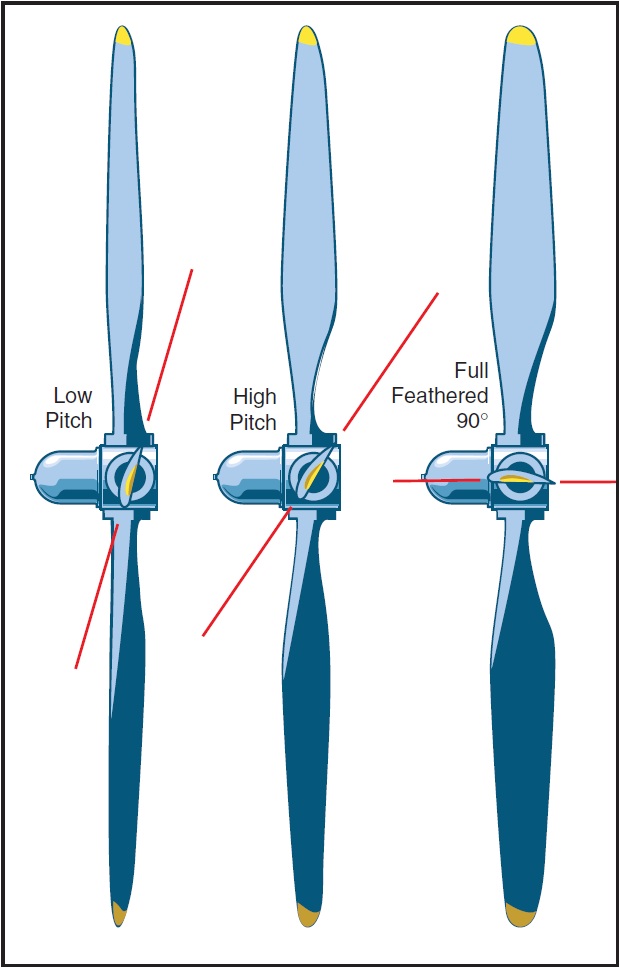
The propellers of the multiengine airplane may outwardly appear to be identical in operation to the constant-speed propellers of many single-engine airplanes, but this is not the case. The propellers of multiengine airplanes are featherable, to minimize drag in the event of an engine failure. Depending upon single-engine performance, this feature often permits continued flight to a suitable airport following an engine failure. To feather a propeller is to stop engine rotation with the propeller blades streamlined with the airplane’s relative wind, thus to minimize drag. [Figure 12-2]

Figure 12-2. Feathered propeller.
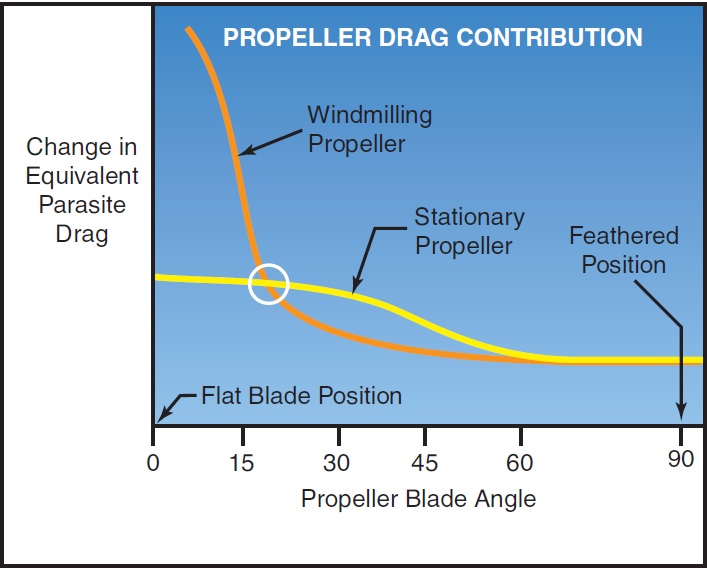
Feathering is necessary because of the change in parasite drag with propeller blade angle. [Figure 12-3] When the propeller blade angle is in the feathered position, the change in parasite drag is at a minimum and, in the case of a typical multiengine airplane, the added parasite drag from a single feathered propeller is a relatively small contribution to the airplane total drag.

Figure 12-3. Propeller drag contribution.
At the smaller blade angles near the flat pitch position, the drag added by the propeller is very large. At these small blade angles, the propeller windmilling at high r.p.m. can create such a tremendous amount of drag that the airplane may be uncontrollable. The propeller wind- milling at high speed in the low range of blade angles can produce an increase in parasite drag which may be as great as the parasite drag of the basic airplane. As a review, the constant-speed propellers on almost all single-engine airplanes are of the non-feathering, oil-pressure-to-increase-pitch design. In this design, increased oil pressure from the propeller governor drives the blade angle towards high pitch, low r.p.m.
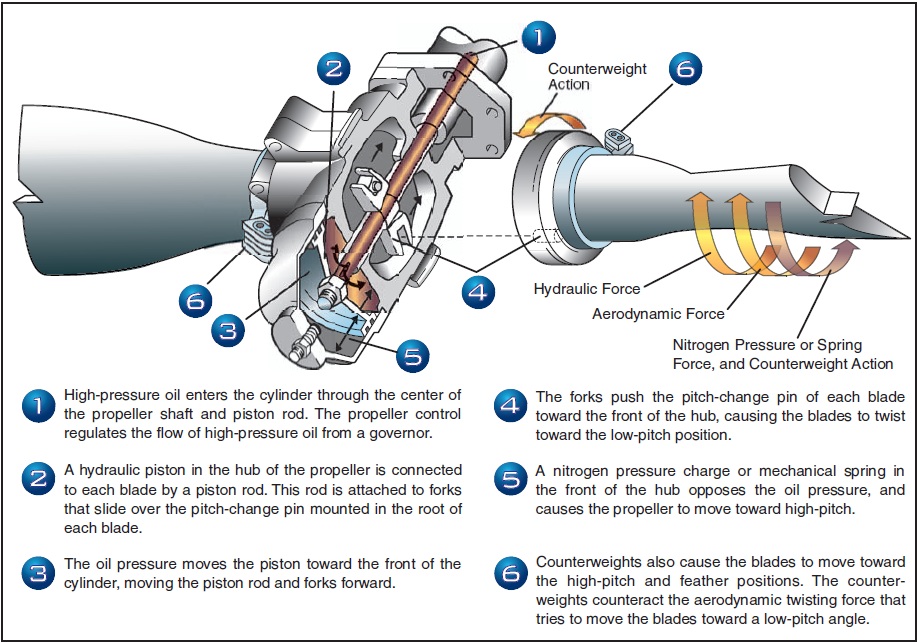
In contrast, the constant-speed propellers installed on most multiengine airplanes are full feathering, counterweighted, oil-pressure-to-decrease-pitch designs. In this design, increased oil pressure from the propeller governor drives the blade angle towards low pitch, high r.p.m.—away from the feather blade angle. In effect, the only thing that keeps these propellers from feathering is a constant supply of high pressure engine oil. This is a necessity to enable propeller feathering in the event of a loss of oil pressure or a propeller governor failure.
Ch 12.qxd 5/7/04 9:54 AM Page 12-4
The aerodynamic forces alone acting upon a wind- milling propeller tend to drive the blades to low pitch, high r.p.m. Counterweights attached to the shank of each blade tend to drive the blades to high pitch, low r.p.m. Inertia, or apparent force called centrifugal force acting through the counterweights is generally slightly greater than the aerodynamic forces. Oil pressure from the propeller governor is used to counteract the counterweights and drives the blade angles to low pitch, high r.p.m. A reduction in oil pressure causes the r.p.m. to be reduced from the influence of the counterweights. [Figure 12-4] To feather the propeller, the propeller control is brought fully aft. All oil pressure is dumped from the governor, and the counterweights drive the propeller blades towards feather. As centrifugal force acting on the counterweights decays from decreasing r.p.m., additional forces are needed to completely feather the blades. This additional force comes from either a spring or high pressure air stored in the propeller dome, which forces the blades into the feathered position. The entire process may take up to 10 seconds.
Feathering a propeller only alters blade angle and stops engine rotation. To completely secure the engine, the pilot must still turn off the fuel (mixture, electric boost pump, and fuel selector), ignition, alternator/generator, and close the cowl flaps. If the airplane is pressurized, there may also be an air bleed to close for the failed engine. Some airplanes are equipped with firewall shutoff valves that secure several of these systems with a single switch.
Completely securing a failed engine may not be necessary or even desirable depending upon the failure mode, altitude, and time available. The position of the fuel controls, ignition, and alternator/generator switches of the failed engine has no effect on aircraft performance. There is always the distinct possibility of manipulating the incorrect switch under conditions of haste or pressure.
To unfeather a propeller, the engine must be rotated so that oil pressure can be generated to move the propeller blades from the feathered position. The ignition is turned on prior to engine rotation with the throttle at low idle and the mixture rich. With the propeller control in a high r.p.m. position, the starter is engaged. The engine will begin to windmill, start, and run as oil pressure moves the blades out of feather. As the engine starts, the propeller r.p.m. should be immediately reduced until the engine has had several minutes to warm up; the pilot should monitor cylinder head and oil temperatures.

Figure 12-4. Pitch change forces.
12-4
Ch 12.qxd 5/7/04 9:54 AM Page 12-5
Should the r.p.m. obtained with the starter be insufficient to unfeather the propeller, an increase in airspeed from a shallow dive will usually help. In any event, the AFM/POH procedures should be followed for the exact unfeathering procedure. Both feathering and starting a feathered reciprocating engine on the ground are strongly discouraged by manufacturers due to the excessive stress and vibrations generated.
As just described, a loss of oil pressure from the propeller governor allows the counterweights, spring and/or dome charge to drive the blades to feather. Logically then, the propeller blades should feather every time an engine is shut down as oil pressure falls to zero. Yet, this does not occur. Preventing this is a small pin in the pitch changing mechanism of the propeller hub that will not allow the propeller blades to feather once r.p.m. drops below approximately 800. The pin senses a lack of centrifugal force from propeller rotation and falls into place, preventing the blades from feathering. Therefore, if a propeller is to be feathered, it must be done before engine r.p.m. decays below approximately 800. On one popular model of turboprop engine, the propeller blades do, in fact, feather with each shutdown. This propeller is not equipped with such centrifugally-operated pins, due to a unique engine design.
An unfeathering accumulator is an optional device that permits starting a feathered engine in flight without the use of the electric starter. An accumulator is any device that stores a reserve of high pressure. On multiengine airplanes, the unfeathering accumulator stores a small reserve of engine oil under pressure from compressed air or nitrogen. To start a feathered engine in flight, the pilot moves the propeller control out of the feather position to release the accumulator pressure. The oil flows under pressure to the propeller hub and drives the blades toward the high r.p.m., low pitch position, whereupon the propeller will usually begin to windmill. (On some airplanes, an assist from the electric starter may be necessary to initiate rotation and completely unfeather the propeller.) If fuel and ignition are present, the engine will start and run. For airplanes used in training, this saves much electric starter and battery wear. High oil pressure from the propeller governor recharges the accumulator just moments after engine rotation begins.
PROPELLER SYNCHRONIZATION
Many multiengine airplanes have a propeller synchronizer (prop sync) installed to eliminate the annoying “drumming” or “beat” of propellers whose r.p.m. are close, but not precisely the same. To use prop sync, the propeller r.p.m. are coarsely matched by the pilot and the system is engaged. The prop sync adjusts the r.p.m. of the “slave” engine to precisely match the r.p.m. of the “master” engine, and then maintains that relationship. The prop sync should be disengaged when the pilot selects a new propeller r.p.m., then re-engaged after the new r.p.m. is set. The prop sync should always be off for takeoff, landing, and single-engine operation. The AFM/POH should be consulted for system description and limitations.
A variation on the propeller synchronizer is the propeller synchrophaser. Prop sychrophase acts much like a synchronizer to precisely match r.p.m., but the synchrophaser goes one step further. It not only matches r.p.m. but actually compares and adjusts the positions of the individual blades of the propellers in their arcs. There can be significant propeller noise and vibration reductions with a propeller synchrophaser. From the pilot’s perspective, operation of a propeller synchronizer and a propeller syncrophaser are very similar. A synchrophaser is also commonly referred to as prop sync, although that is not entirely correct nomenclature from a technical standpoint.
As a pilot aid to manually synchronizing the propellers, some twins have a small gauge mounted in or by the tachometer(s) with a propeller symbol on a disk that spins. The pilot manually fine tunes the engine r.p.m. so as to stop disk rotation, thereby synchronizing the propellers. This is a useful backup to synchronizing engine r.p.m. using the audible propeller beat. This gauge is also found installed with most propeller synchronizer and synchrophase systems. Some synchrophase systems use a knob for the pilot to control the phase angle.
PED Publication